

Table of contents
- Introduction.
- Theories about DC charging circuits.
- Challenges I Thought of while I was about to construct a new Charging Circuit.
- Every CELL PHONE CHARGING CIRCUIT.
- HOW TO BUILD A CHARGING CIRCUIT.
- Conclusion.

Are you a tech enthusiast who have always wondered how charging circuits work? Are you a tech savvy person who has at a certain point in time, thought of how to create his own charging circuit? I'm guessing that by now you would have made extensive researches but still have not gotten a very good answer. This is because I also did, but I could not get a good and well defined solution. Therefore I decided to try out several tests myself until I got the perfect answer. If you're someone also looking for a solution, then you have come to the right place. First let me tell you my story:
Back then long time ago, I always had a lamp, This lamp can only be recharged using solar, i.e it was a solar rechargeable lamp. I loved this lamp it was what I would turn on all through the night until the next morning. Then, one beautiful morning, I set my solar lamp outside for it to charge. On returning that evening I couldn't find my lamp any longer. I was grieved as I didn't know who could have taken my lamp. I then decided to gather money to get a new one.
I finally got a new solar lamp after about a week, I was happy and used my thing, putting it outside somewhere safe in the morning and taking it in back at night. But then, the same unfortunate event which took place first time repeated itself again. This time I got mad, enraged. I questioned everyone who I knew could possibly come to my yard, but noone confessed, or could tell who stole my lamp.
I was like Jeez! Again??
Now this must not repeat itself again. Right?
So this time, the solar lamps available in both online and offline stores were still the ones that can be recharged through solar only. They had no charging ports. I started wondering what if I could set up a charging port in the solar lamp? You may be thinking by now that why couldn't I get an electric rechargeable lamp instead of getting a solar lamp, this is because of the state of poor electricity condition in my area back then. If I get the one that charges with electricity only with no other option to recharge it, I may end up spending several black nights.
This marked the start of my research, How to build an electric recharging circuit/system.
The First theory I had in mind and I want you to note, is that “Any device/gadget that uses a rechargeable battery can most definitely be recharged using electricity”. Regardless the type of device it is, as long as the battery is not a primary cell battery, it can be recharged using a wall charger.
The second theory I had in mind and I also want you to note is that “Every charging system starts with a charging connector/charging dock and ends with the battery” i.e electric current is supplied via the charging connector, and it's endpoint or delivery point is the battery.
The Third theory I had in mind also was “Many mobile Phones chargers supply/inject a charge voltage of 5V into the charging connector and the voltage required to charge a battery is 4.2V”. These are the theories I had in mind before conducting my research.
CHALLENGES I THOUGHT OF WHILE I WAS ABOUT TO CONSTRUCT A NEW CHARGING CIRCUIT:
1. How would I step down charge input voltage of 5v to battery charge voltage of 4.2v.
2. How can I do it that if I build my charging circuit with the battery as the endpoint, there would be no back-flow of current from the battery back to the charging connector.
I was finally able to overcome these challenges with just a simple knowledge, what did I say? just a simple knowledge. I was able to build the perfect charging circuit after seriously studying the charging circuit of Mobile Phones.
CELL PHONE CHARGING CIRCUIT:
•Every mobile phone charging system starts with a charging connector through which voltage is injected. The wireless charging system create a charging voltage by redistributing the +ve and -ve charges into their respective terminals, the same goes for a solar charging system.
•The voltage injected through the charging connector goes through a capacitor which filters/purifies the Direct Current coming in. A capacitor has two terminals, the positive terminal and the negative terminal which we know as ground terminal. The voltage passes through the positive terminal or the positive line, while the negative terminal serves as the reference/ground point.
•After the current has passed through the capacitor, I want to digress a little bit, I noticed in Samsung phones that there're resistors through which the current goes through after passing the capacitor. These resistors perform the major function of voltage control using temperature change. The higher the voltage, the higher the resistance of the resistor; and the higher the resistance of a resistor, the higher the heat generated by the resistor. The same way the lower the voltage the lower the resistance of the resistor. These resistors are therefore known as Thermistors. They regulate the injected voltage to prevent charge over-voltage and charge under-voltage. Whenever these resistors oppose a high voltage, the high temperature generated goes through lines to the CPU and this is what cause the pop up “Charging Voltage/Temperature too high” and “charging Voltage/Temperature too low” in so many Samsung phones these days. In a situation where the appropriate voltage is injected through a specified charger and the phone still brings up this pop up, then the thermistor(s) is in for a change.
Now back to where we are, thermistors are not regularly used along the charging system of iPhones and other Androids so we skip the aspect of themistors while building our charging circuit.
•Passing through the capacitor, and the thermistor in some phones, the current now comes to a major point we know as the vbus. This does not concern us that much since we're building our charging circuit and do not need any major point.
•After going through the vbus point, the current goes through a major component called the “charging IC”. Now, this is the component that actually does the work of the two challenges I stated up earlier. The charging IC steps down charge voltage from injected voltage of 5v to a safe battery charge voltage of 4.2v. In phones that have fast charging technology the charging voltage is more than this, and this is because the battery has been programmed in such a way that it can adapt to high voltages. This is why if one uses a fast charge or high output charger to charge a iPhone or any smartphone or gadget, the battery/charging IC suffers and becomes spoilt; too much voltage. The charging IC also has lines that goes to the CPU to tell your phone that it is charging. Once this line is open/damaged, there will be a problem where your phone will be charging but it won't show the charging sign. The charging IC on iPhones is called Tigris and Hydra.
•After passing through the charging IC, the voltage is stepped down, and this time, taken along the battery positive line. Goes through the major point vbat, and then finally to the battery connector to charge the battery.
This is how the charging system/circuit of every phone/gadget looks like. For Laptops: it follows the same procedure. Alternating current from the Wall socket is converted to Direct Current with the aid of a rectifier. The direct current is then purified through a charge system as described earlier, which then recharges the battery.
Now that we have understood how the charging system/circuit of every gadget works, we can now build our own circuit from scratch.
HOW TO BUILD A CHARGING CIRCUIT:
Pls note that if you don't have soldering skills you can't do this.
Requirements are :
•Charging port/connector (micro USB or Type-C or Pin-mouth).
•Soldering iron, soldering paste, jumper wire and solder.
•Charging IC or a Zener Diode(5.1v).
•Multimeter.
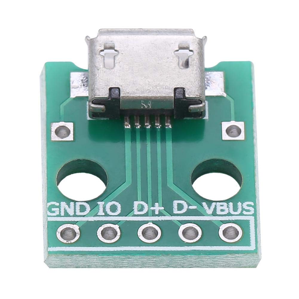
1.we start with the charging connector, a micro USB connector has five legs, USB Type-C has 12 while pin mouth has only two. These connectors have positive and the negative terminals/leg. For micro USB it is the first leg and last leg, for USB Type-C it is first and fourth or ninth and last while for pin mouth it is only the two.

How do you differentiate/determine the positive terminal/leg and the negative terminal/leg:
•We make use of a multimeter to determine the positive and negative terminals/legs.
•Insert a charger into the connector, then switch the multimeter to the DC Volts setting(the V sign with three short horizontal lines on top of it). Take out the two probes of your multimeter. Place the red probe on one leg and the black probe on the other leg. The voltage supplied by the charger reads on the multimeter. If it doesn't then you're doing it wrongly, restart the process.
•After the voltage reads on the multimeter, if the voltage is positive, then the leg which the red probe stands on is the positive, and the leg which the black probe stands on is the negative. But if the voltage is negative, then reverse is the case, the leg in the black probe is positive and the leg in the red probe is negative.
2.After this has been done, solder a jumper wire to each terminals/legs of the charging connector. Ensure the jumper wire on the negative leg is longer than that of the positive, and ensure they are firmly soldered, i.e they cannot remove later.
3.Connect the other end of the jumper wire which is soldered on the positive leg, to the positive terminal of the charging IC or positive terminal of a Zener diode which is the Red leg.
4.Then solder another jumper wire on the negative terminal of charging IC or negative(black leg) of Zener diode, connect it to the positive terminal of the battery connector.
5.Last but not the least, connect the jumper wire that was soldered on the negative leg of the charging port to the negative leg of the battery connector. These are ground points/terminals. If you want to have a charging indicator in the form of a LED, connect it's positive terminal to the red leg of the Zener diode, and it's negative terminal to the negative terminal of battery connector (ground).
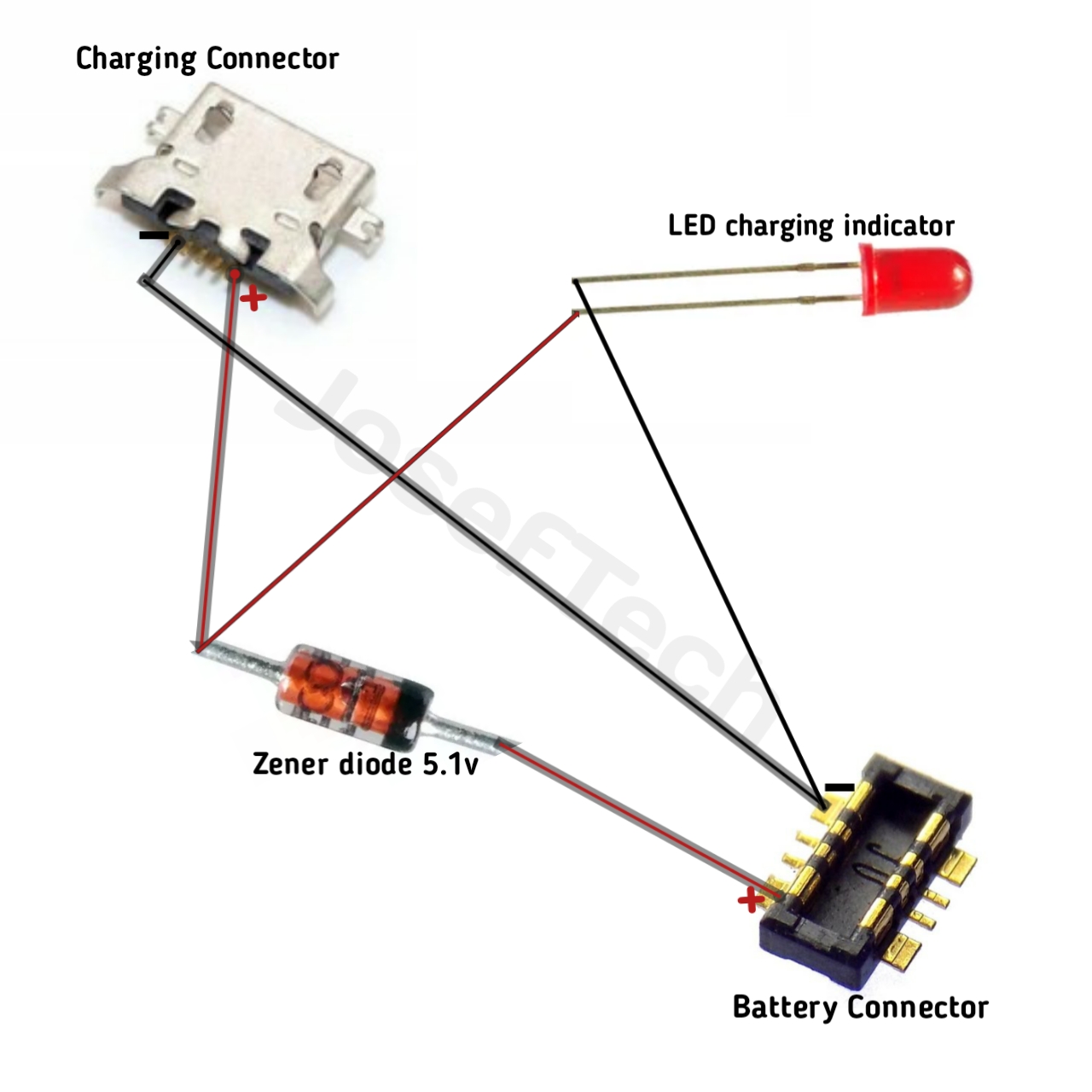 The image above describes the processes to create your own simple charging circuit using a Zener diode as charging IC.
Why can a 5.1V Zener diode be used as a perfect replacement for charging IC?
A charging IC steps down the charge voltage from 5v to 4v and makes the current flow in only one direction which is towards the battery connector. This is because what essentially makes up a charging IC is a network of diodes and capacitors integrated in one component to give rise to a charging IC (integrated circuit). A Zener diode is the basis on which a charging IC is built. A 5.1V Zener diode easily and perfectly performs the function of stepping down voltage from 5v to 4v. This diode will only allow current to pass through it whenever the voltage is more than the threshold voltage which is known as Zener voltage which is 5.1v. Current coming from the charging line has voltage of 5v which easily passes through the Zener diode to charge the battery. But the battery supplies voltage of just 3.7v which is not upto the Zener voltage and therefore cannot be allowed to pass through the Zener diode, therefore there's no current that can have a back-flow to the charging connector. These features of a Zener diode make it a perfect replacement for a charging IC. Zener diodes are sold in every electrical stores and can also be bought online.
Now I've explained how a charging circuit looks like, how it works, and how to build a perfect one. This was how I was able to build my own charging circuit for my lamp so whenever there's light, I charge it using a charger, and whenever there's no light, I charge it using its solar panel in a safe place and I'm telling you my lamp is still alive with me till today, still in use. I've also used my knowledge to construct entirely new charging circuits for several phones with damaged charging circuits . If you have any phone or gadget you want to have a working charging port or circuit that efficiently recharges its battery, this is the way for you. If any part remains unclear to you feel free to let us know through the comment box.


